
Most datasheets are not written like tutorials. They are closer to contracts: dense, precise, and full of assumptions about what the reader already knows.
The trick is not to read every page from top to bottom. The trick is to build a map.
That map should answer six questions before you write firmware or order a board:
- Which exact part and package am I using?
- What voltage, temperature, and current ranges are safe for normal operation?
- Which pins need external components or fixed logic levels?
- Which interface mode and timing limits does the part expect?
- Which registers or commands prove that communication works?
- Which layout or startup notes can silently break the design?
If you read with those questions in mind, the datasheet becomes less like a wall of tables and more like a debugging checklist.
Start with the identity
Before trusting any number, confirm that you are reading the right document for the exact part in front of you.
- Check the full part number, not only the family name.
- Look for package variants, temperature grades, and ordering suffixes.
- Confirm the revision date if the vendor has multiple versions online.
A suffix can change the package, pinout, temperature range, memory size, interface, or factory calibration. Two parts can look almost identical in the title and still behave differently on a PCB.
For example, a sensor family might have one variant with I2C only, another with SPI and I2C, and another with a different pinout in a smaller package. The first page may advertise the whole family, while the ordering table tells you what the specific suffix actually means.
Before doing anything else, write down:
- Full manufacturer part number.
- Package name.
- Supply voltage range.
- Interface variant.
- Expected device ID register, if one exists.
This tiny note becomes your reference while debugging.
Separate limits from design targets
The most expensive beginner mistake is treating Absolute Maximum Ratings as normal operating values.
Absolute maximum ratings tell you where damage may start. They do not tell you where the device is happy, accurate, or reliable. For design work, move to Recommended Operating Conditions.
Use this mental split:
| Section | Meaning | How to use it |
|---|---|---|
| Absolute Maximum Ratings | Survival boundary | Never design here |
| Recommended Operating Conditions | Normal working range | Design here |
| Electrical Characteristics | Behavior inside the normal range | Estimate accuracy, current, timing, thresholds |
If a sensor says VDD absolute maximum is 4.0 V and recommended VDD is 1.8 V to 3.6 V, the design value is not 4.0 V. It is somewhere inside the recommended range.
The same idea applies to input pins. If a digital input has an absolute maximum of VDD + 0.3 V, that does not mean it is safe to drive a 3.3 V signal into a device powered from 1.8 V. You need the recommended logic thresholds, level tolerance notes, or a level shifter.
Field note: 3.0 V, 3.3 V, and 3.7 V are not "close enough"
Early in my embedded career, I did not pay enough attention to the voltage ranges and logic levels that components actually operate in. In my head, 3.0 V, 3.3 V, and 3.7 V felt close enough that I treated them as almost interchangeable.
That mistake cost me an nRF52840 development board.
I had my custom PCB powered over USB from a laptop. The nRF52840 development board was also connected to the laptop, and I wanted to read logs directly through the programmer/debug connection. So I connected the nRF board to my device through the programmer path and started debugging.
What I overlooked was the logic-level mismatch: the nRF side was working around a 3.0 V logic level, while my device was working at 3.3 V. I had treated that difference as harmless. It was not.
After that mistake, the development board was damaged in a very annoying way: it could still run the firmware that was already flashed on it, but it could no longer program itself or program other boards. In other words, the part of the system I relied on for bring-up became the thing I had broken.
The lesson was simple and painful: before connecting two powered systems together, check more than the connector shape and signal names.
- Are both sides using compatible logic levels?
- Are both boards powered at the same time from different USB ports?
- Is there a possible back-power path through signal pins, protection diodes, SWD, UART, or GPIO?
- Are grounds connected in the intended way?
- Does the datasheet allow the voltage present on an input pin when the device is unpowered, resetting, or at a lower VDD?
Since then, I treat logic-level compatibility as part of the datasheet reading process, not as an afterthought. If two boards both say "3 V-ish", I still check the actual operating range, input-high threshold, absolute maximum input rating, and whether I need a level shifter or series protection.
When values look contradictory, trust the section with the narrowest context:
- Recommended operating conditions for normal limits.
- Electrical characteristics for behavior inside those limits.
- Timing tables for interface limits.
- Absolute maximum ratings only as a damage boundary.
Red flags I now search for first
After making enough mistakes, I started scanning datasheets for certain phrases before reading deeply. These phrases usually mean "slow down, this can break hardware or waste a day of debugging."
| Red flag | Why it matters |
|---|---|
| Absolute Maximum Ratings | This is a damage boundary, not a design target. |
| VDD + 0.3 V | Inputs may not tolerate a higher logic level than the supply. |
| Not 5 V tolerant | A common way to damage modern low-voltage parts. |
| Do not leave floating | The pin needs a defined state. |
| Reserved bits | Blind register writes can set undefined behavior. |
| Wait after reset | Talking too early can make a good bus look broken. |
| Dummy byte | The first returned byte may not be valid data. |
| See application circuit | There may be required external components. |
| Exposed pad | It may be electrical, thermal, or both. |
When I see one of these, I copy the note into my bring-up checklist immediately.
Look for hidden external requirements
Datasheets often assume basic support circuitry without repeating it everywhere. You usually need to search for it in application diagrams, layout notes, and pin descriptions.
Watch for:
- Decoupling capacitors on each supply pin.
- Pull-up resistors for open-drain outputs or I2C lines.
- Strap resistors for address, boot, or mode pins.
- Required crystal, load capacitors, or clock source.
- Analog reference pins and filtering.
- Thermal pad connection requirements.
If a pin description says "connect to ground" or "do not leave floating", treat that as a design rule, not a suggestion.
Read pin tables like failure reports
The pinout is not just wiring documentation. It is a list of ways your board can fail.
For every pin, ask:
- Is it input, output, bidirectional, power, analog, or open-drain?
- Does it need a pull-up or pull-down?
- Is it tolerant of the voltage used by the other device?
- Does it have a boot-time or reset-time meaning?
- Does the package variant move or remove this pin?
Boot pins, address select pins, chip select pins, and enable pins deserve extra attention. A floating enable pin can make a perfect firmware driver look broken.
I like to mark pins in four groups:
| Pin type | What to verify |
|---|---|
| Power | Voltage, decoupling, sequencing, current draw |
| Digital interface | Logic level, direction, pull-up/down, alternate function |
| Configuration | Boot mode, address select, enable, reset |
| Analog or RF | Reference, impedance, filtering, layout distance |
This is especially useful when comparing schematic symbols against the datasheet. A schematic can look clean while one mode pin is silently floating.
Timing diagrams are truth tables with time attached
Protocol sections often look intimidating because the timing drawings are visually dense. Read them in layers.
First identify the actors:
- Which device drives the clock?
- Which device drives data?
- Which edge samples data?
- Which edge changes data?
- When does chip select become valid?
Then compare the timing table with your MCU configuration. For SPI, that usually means CPOL, CPHA, maximum clock frequency, chip-select setup time, and chip-select hold time.
A logic analyzer can tell you what happened. The datasheet tells you what was allowed to happen.
Timing diagrams also tell you what your software must not assume. If the datasheet says the device needs 5 ms after reset before the first command, a driver that works on your desk may fail in cold temperature or after a fast power cycle.
Make a small timing note:
- Maximum bus frequency.
- Required delay after power-up.
- Required delay after reset.
- Minimum chip-select high time.
- Whether multi-byte transfers require continuous chip select.
- Whether the first returned byte is dummy data.
Register maps need context
Register tables are easy to skim and easy to misuse. Do not jump straight to the hex values.
Read the notes around the table:
- Which registers are read-only, write-only, or read-clear?
- Which bits are reserved?
- Are writes ignored until a mode bit is set?
- Is there a required delay after reset?
- Does the device need a soft reset, unlock sequence, or page select?
Reserved bits should usually be preserved, not casually written as zero. A safe register write often means read-modify-write, not blind write.
When bringing up a part, avoid starting with the most complicated configuration. First read one stable register:
- Device ID.
- Status register.
- Reset/default value of a readable configuration register.
Only after that should you enable interrupts, FIFO modes, DMA, low-power states, or advanced filters.
Read layout notes before the PCB is finished
Layout guidance is easy to postpone because it appears late in the document. That is dangerous. For switching regulators, ADCs, RF parts, current sensors, USB devices, and high-speed interfaces, layout is part of the circuit.
Common layout rules include:
- Keep decoupling capacitors close to supply pins.
- Separate noisy switching nodes from sensitive analog inputs.
- Use a solid ground return.
- Follow differential pair impedance and length guidance.
- Connect exposed pads as specified.
- Keep sense traces away from high-current paths.
If a datasheet includes a recommended layout image, treat it as design input. Do not wait until the board is routed to read it.
Build a small checklist before debugging
When a device does not respond, walk the datasheet in this order:
- Power rails and recommended voltage range.
- Reset and enable pins.
- Required startup delay.
- Interface mode and address or chip select.
- Logic-level compatibility.
- Timing limits.
- First expected ID register or status register.
This checklist saves time because it keeps you from debugging firmware while the hardware is still asleep.
Add two more checks when the interface looks alive but values are wrong:
- Verify byte order and bit order.
- Verify scaling formulas and unit conversions.
Many sensors return raw values that need sign extension, calibration constants, or LSB-per-unit scaling. A wrong conversion can look like noisy hardware.
A useful reading order
For a new part, this is the order I like:
- Title page and feature summary.
- Ordering information and package options.
- Pin configuration and pin descriptions.
- Recommended operating conditions.
- Electrical characteristics.
- Interface timing.
- Register map or command set.
- Application notes and layout guidance.
Only after that do I read the long functional description in detail.
Before I power a new board
Before connecting a new PCB to USB, a programmer, or another board, I like to do a short "do not destroy anything" pass.
- Confirm the expected supply voltage.
- Confirm the supply polarity.
- Check for shorts between power and ground.
- Use a current-limited supply for first power when possible.
- Confirm the programmer/debugger target voltage.
- Confirm IO voltage compatibility between boards.
- Check whether any signal can back-power an unpowered device.
- Confirm reset and boot pins are not floating.
- Confirm exposed pads and grounds are connected as intended.
This list is boring. That is exactly why it works. The worst hardware mistakes often happen before the interesting firmware debugging even starts.
How to use an AI datasheet chat safely
AI can speed up datasheet reading, but only if it gives you source-cited answers and you still verify critical values.
This is one of the reasons I am building Zeptrion. I do not want an AI tool that simply says "the voltage is probably 3.3 V" and leaves me guessing where that came from. For embedded work, the useful version is an answer that points back to the exact datasheet page, table, or paragraph.
Zeptrion helps most when the datasheet is long and you already know what kind of answer you need. Instead of searching through 80 pages manually, I can ask a narrow question, inspect the cited chunks, and open the original PDF page next to the answer.
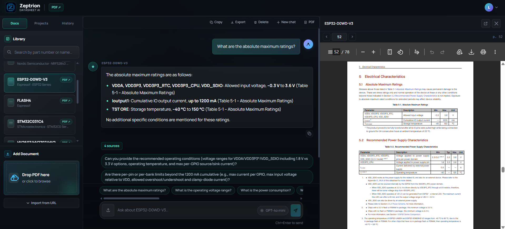
Zeptrion keeps the answer and the cited datasheet page visible together, so values can be checked against the original source.
That changes the workflow from:
- Search the PDF for five different words.
- Jump between sections.
- Copy values into notes.
- Wonder whether a table was about absolute limits or recommended conditions.
Into something closer to:
- Ask one focused engineering question.
- Read the short answer.
- Open the cited source page.
- Verify the value in the original table.
- Save the result into a bring-up checklist.
Good questions are specific:
- "What is the recommended supply voltage range? Cite the section."
- "Which pins must not be left floating?"
- "What SPI mode and maximum clock frequency does this part require?"
- "Is there a required delay after reset before reading registers?"
- "Which register contains the device ID and what value should I expect?"
Weak questions are vague:
- "How do I use this chip?"
- "Is this safe?"
- "Write the whole driver."
For hardware work, the best AI answer is not just a paragraph. It is a pointer back to the exact datasheet section that you can inspect.
Where Zeptrion fits into the reading map
I think of Zeptrion as a second pair of eyes while building the map from the beginning of this article.
| Task | How Zeptrion helps |
|---|---|
| Identify the part | Ask for manufacturer, part number, package, and family clues. |
| Separate limits | Ask for recommended operating conditions separately from absolute maximum ratings. |
| Check pins | Ask which pins require pull-ups, fixed levels, decoupling, or special layout. |
| Read timing | Ask for SPI/I2C/UART timing constraints and cite the table. |
| Bring-up registers | Ask for device ID, reset values, and required startup delays. |
| Compare sections | Ask whether two values are from different sections or operating assumptions. |
The key is that Zeptrion should not replace the datasheet. It should shorten the path to the right part of the datasheet.
For example, these questions are much more useful when they are specific:
| Weak question | Better question |
|---|---|
| Can I use this chip? | What are the recommended operating voltage ranges, and how do they differ from the absolute maximum ratings? Cite the tables. |
| Why does SPI not work? | Which SPI mode, maximum clock, and chip-select timing does this datasheet require? |
| What pins do I connect? | Which pins require pull-ups, fixed levels, decoupling capacitors, or special layout? |
| Is this value safe? | Which section gives this value, and is it an absolute maximum rating or a recommended operating condition? |
| How do I start the driver? | Which register can I read first to confirm communication, and what value should I expect after reset? |
Those questions produce answers that are easier to verify. If the answer cites a page, I can open the PDF panel and check whether the table, units, and section title match what I intend to design around.
Zeptrion is especially useful for avoiding one subtle mistake: mixing values from different contexts. A current limit might be cumulative for the whole port, a voltage might be an absolute stress rating, and a timing value might apply only at a specific supply voltage. A good source-cited workflow makes those context shifts more visible.
Quick review template
Before you consider a datasheet "read", fill this out:
| Item | Notes |
|---|---|
| Exact part number | |
| Package | |
| Supply voltage | |
| Logic voltage | |
| Interface | |
| Startup delay | |
| Device ID register | |
| Required external parts | |
| Layout warnings |
This takes a few minutes and prevents hours of confused debugging later.
Takeaway
A datasheet is not one document. It is a stack of constraints. Read it by separating identity, limits, operating range, pins, timing, and registers. Once those pieces are clear, the rest of the document becomes much less hostile.